
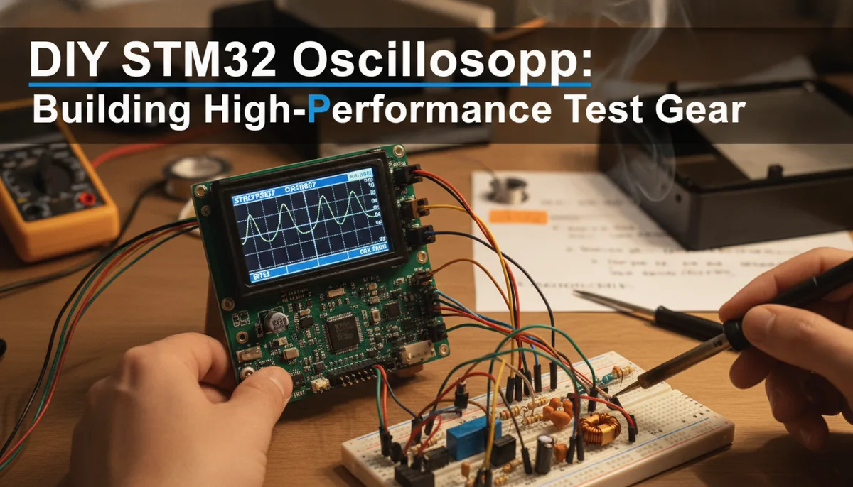
DIY STM32 Oscilloscope: Building High-Performance Test Gear with the STM32F207
The Evolution of the DIY Workbench
For many electronics hobbyists, the transition from a simple multimeter to an oscilloscope marks a significant milestone in their technical journey. While a multimeter provides a static snapshot of voltage or current, an oscilloscope offers a window into the temporal behavior of a circuit. However, professional-grade oscilloscopes can be a significant investment. This has led to a surge in interest in DIY solutions, specifically those leveraging the power of modern 32-bit microcontrollers.
The STM32 family, particularly the STM32F207, has become a favorite for these projects. Unlike basic 8-bit microcontrollers, these ARM Cortex-M based chips offer high-speed Analog-to-Digital Converters (ADCs) and sophisticated Direct Memory Access (DMA) controllers, making them capable of capturing signals that would be invisible to lesser hardware. If you are already familiar with modifying your existing tools, such as Wireless LCD Streaming for the ANENG AN870: A Deep Dive into Multimeter Hacking, building a custom oscilloscope is the logical next step in expanding your diagnostic capabilities.
Understanding the Heart of the Scope: The STM32F207 ADC
The performance of any oscilloscope is primarily dictated by its ADC. In the project developed by [BTTLab], the internal ADC of the STM32F207 is pushed to its functional limits to create a single-channel diagnostic tool.
Sampling Rate vs. Bandwidth
The STM32F207 features a 12-bit ADC capable of reaching roughly 2 MSPS (Mega Samples Per Second). To put this in perspective, a standard entry-level professional scope like the Rigol DS1054Z hits 1 GSPS (Giga Samples Per Second). While the difference is massive, 2 MSPS is surprisingly capable.
According to the Nyquist-Shannon sampling theorem, you need to sample at least twice as fast as the highest frequency component of the signal you wish to capture. In practice, for a visual representation that is actually useful, you want a sampling rate 5 to 10 times higher than the signal frequency. This means an STM32-based scope is perfectly suited for signals in the 200 kHz to 400 kHz range—covering most audio applications, low-speed PWM, and basic sensor communications.
STM32F207 Discovery Development Board
Resolution and Precision
At 12-bit resolution, the ADC can divide the voltage range (typically 0-3.3V) into 4,096 discrete levels. This provides a much finer "vertical" resolution than the 8-bit ADCs found in many entry-level digital storage oscilloscopes (DSOs), which only offer 256 levels. This makes the STM32 an interesting choice for precision analog work where voltage accuracy is more critical than raw speed.
The Critical Importance of the Front-End Circuit
One of the most common mistakes when building a DIY oscilloscope is connecting a signal source directly to the MCU pins. The internal ADC of an STM32 is fragile; it is designed to operate within a strict window, usually 0V to 3.3V.
Avoiding the "Magic Smoke"
If you attempt to measure a standard 12V automotive signal or the negative swing of an AC audio signal directly, you risk immediate hardware failure—often referred to in the community as "releasing the magic smoke."
A proper front-end circuit serves three primary purposes:
- Attenuation: Scaling high voltages (like 12V or 24V) down to the 3.3V range.
- Level Shifting: Adding a DC offset to AC signals so that the negative portion of the wave sits above 0V.
- Protection: Using clamping diodes to ensure that even if a transient spike occurs, the voltage at the MCU pin never exceeds its rated limits.
For those looking to build this project on a breadboard or custom PCB, having a reliable soldering setup is essential for ensuring signal integrity in the front-end. You can find our recommendations for high-quality tools in our Best Portable Soldering Irons of 2024: A Field Guide.
Firmware Architecture: Leveraging ST HAL and DMA
The software side of the [BTTLab] project utilizes the ST Hardware Abstraction Layer (HAL). While some purists prefer direct register access for maximum speed, the HAL provides a balance of readability and portability.
The Role of DMA
In a high-speed data acquisition system, the CPU should not be responsible for moving every single sample from the ADC to memory. If it were, the processor would have no cycles left to handle the user interface or data processing.
By using Direct Memory Access (DMA), the ADC can "dump" its samples directly into a buffer in the SRAM. The CPU is only notified via an interrupt once the buffer is full. This architecture allows the STM32F207 to maintain a consistent 2 MSPS without dropped samples, even while refreshing a display or calculating FFT (Fast Fourier Transform) data.
USB Logic Analyzer 24MHz 8 Channel
Portability Across the STM32 Ecosystem
Because the project uses the ST HAL, the firmware can, in theory, be ported to other chips like the STM32F4 or F7 series. However, developers must be cautious. ADC implementations vary significantly between families. Some higher-end STM32 MCUs feature multiple ADCs that can be "interleaved" to effectively double or triple the sampling rate, potentially pushing a DIY project toward the 5-10 MSPS mark.
Practical Use Cases for a 2 MSPS Oscilloscope
While you won't be debugging high-speed USB or DDR memory with an STM32-based scope, there are several areas where this DIY tool excels:
- Audio Electronics: Troubleshooting amplifiers, pedals, and synthesizers where signals rarely exceed 20 kHz.
- Power Electronics: Monitoring the output of DC-DC converters and PWM motor controllers.
- Education: Understanding the fundamentals of sampling, triggering, and aliasing without the cost of professional gear.
- Protocol Debugging: While a logic analyzer is better for digital data, a scope allows you to see the "physical layer"—checking for ringing, slow rise times, or noise on I2C and UART lines.
For those looking to build out a complete mobile laboratory, integrating this DIY scope with other portable tools is a great way to stay productive in the field. Check out The Soldered Anywhere Master Buying Guide for a curated list of essential gear that complements a DIY-heavy workflow.
Conclusion: Is the STM32 Oscilloscope Worth It?
Building an oscilloscope from an STM32F207 is less about replacing a Rigol or Siglent and more about the mastery of embedded systems. It forces the developer to grapple with real-world constraints: ADC noise floors, DMA buffer management, and the nuances of analog front-end design.
For the hobbyist, the [BTTLab] project provides a solid foundation. It demonstrates that with a few dollars' worth of silicon and some well-structured code, you can create a tool that is genuinely useful for a wide array of electronics tasks. Whether you are looking to save money or simply want to understand your tools from the inside out, the DIY STM32 oscilloscope is a project that delivers immense educational value.
2xFor BNC Oscilloscope Probe Kit...
Related product: STM32F746G-DISCO STM32 Discovery...
Related product: USB Logic Analyzer 24MHZ 8 Chann...
Related product: 2xFor BNC Oscilloscope Probe Kit...
Related product: STM32F746G-DISCO STM32 Discovery...
Related product: USB Logic Analyzer 24MHZ 8 Chann...