
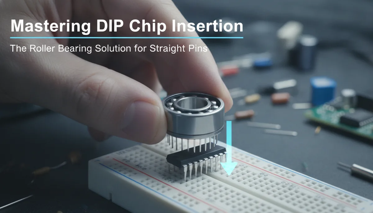
Mastering DIP Chip Insertion: The Roller Bearing Solution for Straight Pins
The DIP Chip Dilemma: Why Pins Aren't Straight
If you have ever unboxed a brand-new Dual Inline Package (DIP) integrated circuit, you have likely noticed a frustrating physical trait: the pins are rarely perfectly vertical. Instead, they flare outward at a slight angle. For the uninitiated, this looks like a manufacturing defect. For the seasoned assembler, it is the "bane of many assemblers," as noted by the Tynemouth Blog.
This outward flare is actually intentional. Integrated circuits are designed to be compatible with automated "pick-and-place" and insertion machines. The slight angle provides a spring-like tension that keeps the chip securely seated in a PCB or a socket before it passes through a wave soldering machine.
However, for the hobbyist, engineer, or retro-computing enthusiast working by hand, this flare is a recipe for disaster. When you attempt to press a flared IC into a high-quality machined socket or a tight breadboard, the pins often catch on the edges. If you apply too much force, a pin may buckle, folding underneath the body of the chip. At best, you have to pull it out and try again; at worst, the pin snaps off, rendering an expensive or rare component useless.
The Risks of Manual "Table-Top" Straightening
The most common "field fix" for flared pins is the table-top roll. This involves placing one side of the IC pins against a flat, hard surface and rocking the chip body forward to bend the pins inward. While this is better than nothing, it is fraught with precision issues:
- Uneven Pressure: It is nearly impossible to apply perfectly even pressure across all 8, 14, or 40 pins. You often end up with a "wave" pattern where the center pins are straight but the end pins remain flared.
- Over-Bending: Without a physical stop, it is easy to bend the pins past the 90-degree mark. Bending them back out weakens the metal, leading to "metal fatigue" and eventual breakage.
- ESD Risks: Rolling a sensitive CMOS chip across a standard laminate desk generates static electricity. Without proper grounding, you risk zapping the internal logic of the chip before it even touches a circuit.
To achieve professional results, especially when working on high-density boards, a dedicated tool is required. This is where the innovation of the roller bearing IC leg straightener comes into play.
Enter the Roller Bearing IC Pin Straightener
Recently highlighted by the Tynemouth Blog and featured via Adafruit, the roller bearing solution represents a significant upgrade over the cheap, plastic "squeeze" tools that have dominated the market for decades.
A roller bearing straightener typically consists of two parallel metal rollers housed in a sturdy frame. The gap between these rollers is precision-calibrated to the exact width of a standard DIP package (usually 0.3 inches for small ICs or 0.6 inches for larger ones like CPUs and EPROMs).
Why Rollers Matter
Unlike static blocks or plastic pliers, rollers reduce friction. As you slide the IC through the tool, the bearings rotate, gently "massaging" the pins into a vertical position without scraping the plating off the legs. This is particularly important for vintage chips where the leg plating may be brittle or prone to oxidation.
When selecting tools for your bench, it is helpful to look at comprehensive resources like The Soldered Anywhere Master Buying Guide to see how specialized alignment tools fit into a broader assembly workflow.
How to Use a Roller Bearing Straightener Safely
Using these tools is straightforward, but there are nuances to ensuring you don't damage your components.
1. Identify the Width
DIP chips come in two primary widths: "Skinny" DIP (0.3 inch) and "Wide" DIP (0.6 inch). Most roller bearing tools are designed for the 0.3-inch standard used by logic gates, op-amps, and small microcontrollers. If you are working on vintage 6502 or Z80 processors, you will need a wider version of the tool.
2. Alignment and Orientation
Place the IC into the entry slot of the tool. Ensure the "notch" or "dot" (indicating Pin 1) is facing a direction that allows you to keep track of orientation, though the straightening process itself is non-directional. Ensure the body of the chip is centered between the rollers.
3. The Pass-Through
Gently push the chip through the rollers. You should feel a slight resistance as the rollers compress the flared pins toward the center. A single pass is usually sufficient. If the pins were severely deformed, a second pass may be necessary, but avoid "over-working" the metal.
4. Verification
After the pass, hold the chip at eye level. The pins should now be perfectly parallel to each other and perpendicular to the chip body. They should drop into a breadboard or socket with zero resistance.
Beyond Straightening: Best Practices for IC Insertion
Straightening the pins is only half the battle. Successful PCB assembly requires a holistic approach to component handling.
ESD Safety
Even with a high-quality tool, static is your enemy. Always use an ESD-safe workstation. If your pin straightener is made of metal, ensure it is resting on a grounded ESD mat. When you are working in the field or away from a traditional bench, your choice of soldering iron and environment matters. For those who prioritize a portable yet professional setup, the Pinecil V2 Review: Is the Hype Actually Real? explores how modern portable tools handle sensitive components.
Socket Selection
If you are building a project that may require chip replacements (like a BIOS chip or a microcontroller), always use a socket. However, not all sockets are created equal:
- Dual-Leaf Sockets: Cheap and common, but prone to "springing" open over time.
- Machined (Turned-Pin) Sockets: Highly reliable and provide excellent contact, but they have very tight tolerances. These sockets require perfectly straightened pins; otherwise, you will likely ruin the socket during insertion.
10PCS DIP-8 IC Sockets Machined...
Integrating Specialized Tools into Your Workflow
While a pin straightener might seem like a luxury, it becomes essential as the scale of your projects grows. If you are assembling a kit with 20+ ICs, the time saved—and the reduction in "swearing-per-hour"—is immense.
A professional workflow usually looks like this:
- Preparation: Straighten all IC pins in bulk before starting the soldering process.
- Passive Placement: Solder resistors, capacitors, and diodes first.
- Socketing: Solder the IC sockets.
- Final Insertion: Insert the straightened ICs into the sockets as the final step. This prevents the chips from being exposed to the heat of the soldering iron longer than necessary.
For more tips on refining your soldering technique, especially when working with portable equipment, check out our guide on 5 Essential Solder Tips for Portable Irons: The Ultimate Field Guide.
Is the Roller Bearing Tool Worth It?
For the occasional hobbyist building one project a year, the "table-roll" method might suffice. But for anyone involved in repair, restoration, or small-scale production, the roller bearing IC leg straightener is a "buy once, cry once" tool.
The Tynemouth Blog’s exploration of these tools highlights a shift in the maker community toward precision. As we move away from "good enough" and toward "professional grade," the tools we use must reflect that standard. Whether you are reviving a Commodore 64 or prototyping the next great IoT device, starting with straight pins is the first step toward a reliable, functional circuit.
Conclusion
The "bane of many assemblers" doesn't have to be yours. By understanding the mechanical necessity of flared pins and employing a precision roller bearing tool to correct them, you eliminate one of the most common points of failure in electronics assembly. Invest in the right tools, maintain a static-safe environment, and your PCBs will look—and function—better than ever.
Related product: 10PCS DIP-8 IC Sockets Machined...